Headed Concrete Anchors & Shear Connectors Selection Guide
Headed concrete anchors (HCAs) and shear connectors are drawn arc weld studs designed to transfer load between structural steel and concrete. HCAs anchor embed plates and steel members into concrete slabs and walls; shear connectors create composite action between steel beams and concrete decks. Both use the same stud geometry and welding process -- the distinction is the application and the governing design standard.
- Pick shank diameter and after-weld length (AWL) from the load and embedment your engineer specifies -- then add back the weld loss (about 3/16" to 5/16" depending on diameter) to get the before-weld length to order.
- Direct-plate welding uses standard ferrules; welding through metal deck for composite construction always requires thru-deck (TD) ferrules, not standard ones.
- Shear connectors in composite deck are governed by AWS D1.1 welding requirements and AISC 360 design rules; 3/4" is the practical maximum diameter since larger studs do not add proportional capacity in deck applications.
- Match the ferrule to the stud diameter and application (standard vs. thru-deck) -- see the Weld Stud Ferrule Sizing Chart below for part numbers.
Cox and Bluearc drawn-arc studs, in stock and shipping from Eugene, OR. Buy by the box, or submit a project for job pricing.
Shop HCA & Shear Connector Studs → Get job pricing / submittalsShop Popular Sizes by Diameter
One common in-stock configuration per diameter, ready to add to cart. Prices show without a login. Need a different length or a stainless grade? Browse the full HCA & shear-connector listing or submit the job for pricing.
| Diameter | Popular size | Typical application | Shop |
|---|---|---|---|
| 3/8" | 3/8" x 2-5/8" | Light embed-plate anchoring | Add → |
| 1/2" | 1/2" x 3-1/8" | Embed plates, light shear | Add → |
| 5/8" | 5/8" x 6-9/16" | Composite deck shear connectors | Add → |
| 3/4" | 3/4" x 4-3/16" | Composite deck shear connectors (most common) | Add → |
| 7/8" | 7/8" x 5-3/16" | Heavy shear / precast embedment | Add → |
Eugene Fastener stocks HCA weld studs in carbon steel (ASTM A108) and stainless steel (304, 316) from 1/4" through 1" diameter. We do not stock Nelson-brand studs, but we carry Cox Industries and Bluearc equivalents in most sizes. See our Nelson weld stud cross-reference if you have Nelson part numbers from drawings.
HCA vs. Shear Connector: What Is the Difference?
The terms are often used interchangeably, but engineers typically distinguish them by application:
| Term | Primary Application | Governing Standard | Typical Diameters |
|---|---|---|---|
| Headed Concrete Anchor (HCA) | Embed plates, column base plates, wall ties, anchor channels -- steel anchored into concrete | ACI 318 Chapter 17 | 1/4" to 5/8" |
| Shear Connector | Composite steel beam construction -- welded to top flange through metal deck | AISC 360 Chapter I, AWS D1.1 | 3/4" and 7/8" most common; 1" available |
From a product standpoint, the stud is identical -- same ASTM A108 material, same drawn arc weld end, same head geometry. The difference is diameter range, embedment depth, and what code the structural engineer is designing to.
Stud Geometry: What the Dimensions Mean
Every HCA weld stud has three key dimensions: shank diameter, head diameter, and length. The head is what engages the concrete -- it must meet minimum head-to-shank diameter ratios to develop full bearing capacity.

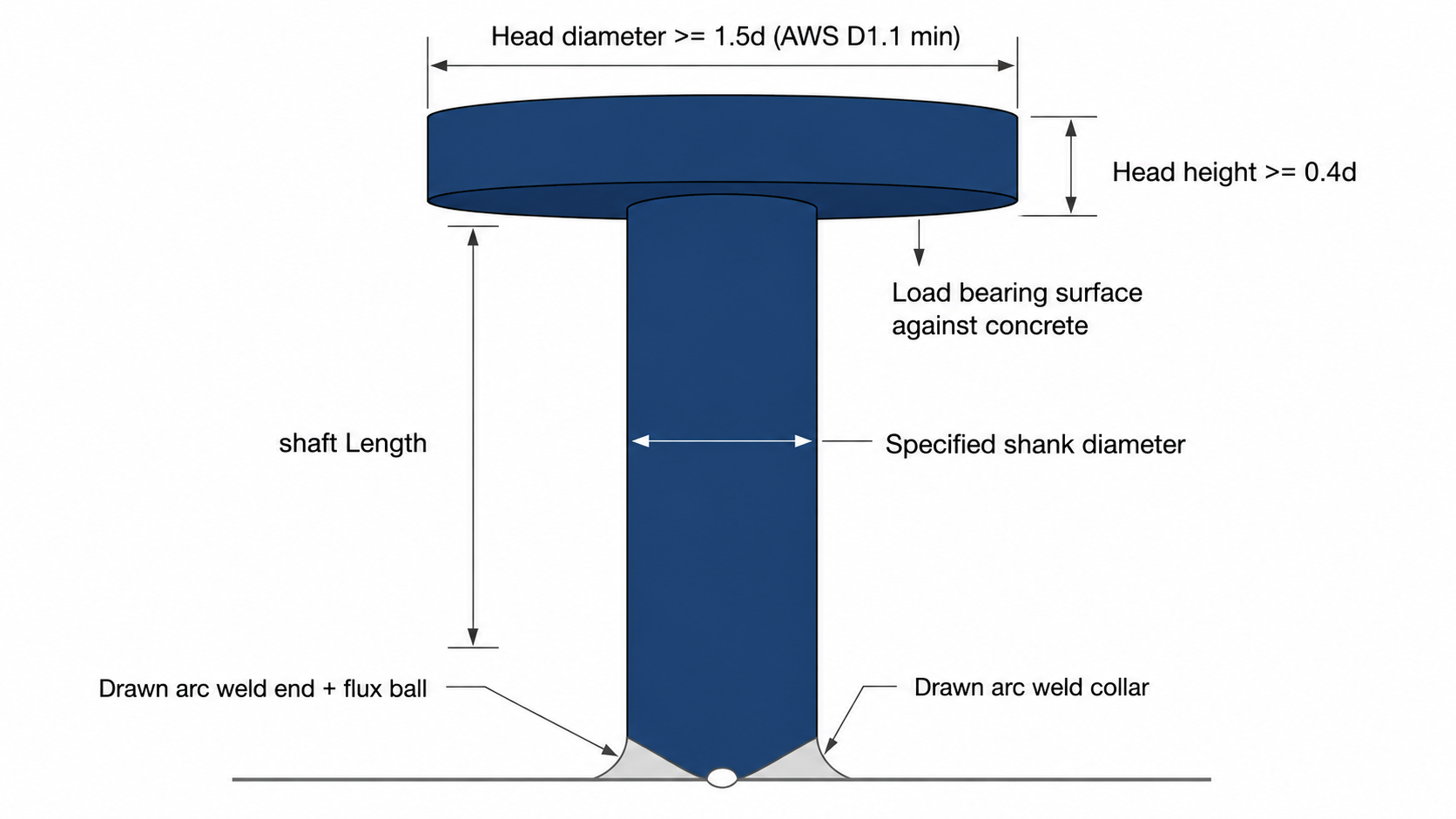
Per AWS D1.1, the head diameter must be at least 1.5 times the shank diameter. The head height must be at least 0.4 times the shank diameter. These minimums ensure the head can develop the full bearing capacity in concrete that the code formulas assume.
| Shank Diameter | Shank Area (in²) | Head Diameter (min) | Standard Head Dia. | Standard Head Height |
|---|---|---|---|---|
| 1/4" | 0.049 | 0.375" | 0.500" | 0.156" |
| 3/8" | 0.110 | 0.563" | 0.625" | 0.188" |
| 1/2" | 0.196 | 0.750" | 0.875" | 0.250" |
| 5/8" | 0.307 | 0.938" | 1.125" | 0.313" |
| 3/4" | 0.442 | 1.125" | 1.250" | 0.375" |
| 7/8" | 0.601 | 1.313" | 1.500" | 0.438" |
| 1" | 0.785 | 1.500" | 1.750" | 0.500" |
Before-Weld Length vs. After-Weld Length
Drawn arc welding consumes material at the weld end. A 1/2" stud welded to a plate will be approximately 3/16" shorter after welding than the catalog-listed before-weld length (BWL). This is called weld loss and must be accounted for when specifying embedment depth.
Structural drawings typically specify after-weld length (AWL) -- the dimension that counts for embedment into concrete. When ordering, check whether the catalog length is BWL or AWL. Eugene Fastener lists before-weld lengths on all product pages; allow for weld loss when confirming embedment requirements.
| Shank Diameter | Typical Weld Loss | Example: 6" BWL = AWL of |
|---|---|---|
| 1/4" to 3/8" | ~3/16" | ~5-13/16" |
| 1/2" to 5/8" | ~3/16" to 1/4" | ~5-13/16" to 5-3/4" |
| 3/4" to 1" | ~1/4" to 5/16" | ~5-3/4" to 5-11/16" |
Weld loss varies by equipment settings, operator technique, and stud diameter. When tolerances are tight, request certified weld loss data from the equipment manufacturer or conduct pre-production qualification welds.
Selecting Diameter and Embedment
The structural engineer of record specifies diameter and embedment based on the required tension, shear, or combined loads per ACI 318 (for HCA applications) or AISC 360 (for composite construction). As a procurement guide, the following rules of thumb apply:
- Minimum embedment depth: For concrete anchoring, ACI 318 requires a minimum embedment of 8 times the stud diameter (8d) for full tension capacity. Reduced embedment requires a breakout capacity reduction.
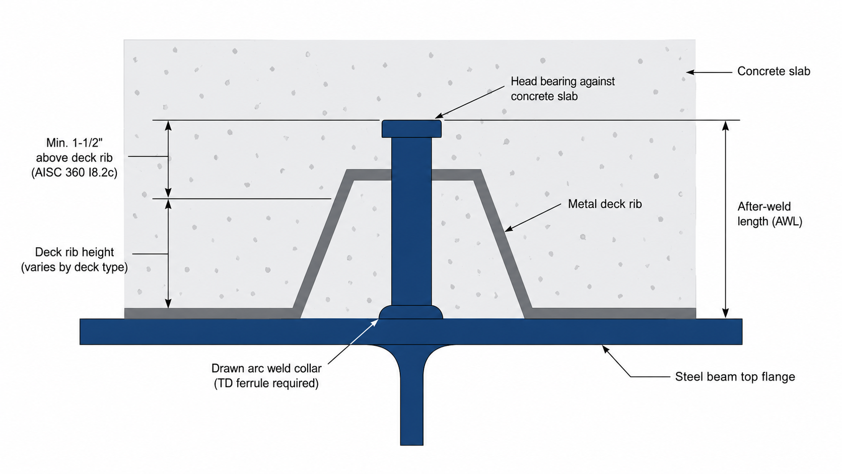
- Composite construction: AISC 360 requires shear connectors to extend at least 1-1/2" above the top of any steel deck rib. After-weld length controls -- verify AWL clears the deck rib plus cover.
- Thru-deck welding: For welding through metal deck, use thru-deck (TD) ferrules, not standard ferrules. The deck creates a standoff that affects the ferrule contact geometry.
- Edge distance: ACI 318 requires minimum edge distance for concrete breakout. Shorter embedment and tighter edge distances reduce capacity -- the engineer calculates these specifically.
Nominal Design Shear Strength by Diameter
The nominal shear strength (Qn) of a headed stud shear connector in solid concrete is governed by AISC 360 Equation I8-1. The values below assume ASTM A108 studs (Fu = 65 ksi) in normal-weight concrete (f'c = 3,000 psi, Ec = 3,320 ksi):
| Shank Diameter | Shank Area (in²) | Qn -- Solid Slab (kips) | Qn -- With Deck, Ribs Parallel (kips) | Qn -- With Deck, Ribs Perpendicular (kips) |
|---|---|---|---|---|
| 1/2" | 0.196 | 11.3 | 11.3 | 8.0 |
| 5/8" | 0.307 | 17.7 | 17.7 | 12.5 |
| 3/4" | 0.442 | 21.0 | 21.0 | 15.7 |
| 7/8" | 0.601 | 21.0 | 21.0 | 15.7 |
| 1" | 0.785 | 21.0 | 21.0 | 15.7 |
Note: Values for 3/4" and larger with deck show the governed (reduced) values per Rg and Rp reduction factors from AISC 360 Table C-I8.2a. Larger diameters do not generate proportionally higher capacity in deck applications -- 3/4" is the standard industry-maximum effective shear connector for composite deck. See the Weld Stud Load Capacities Reference for complete tables.
Material and Grade Selection
Standard HCA weld studs are manufactured from ASTM A108 cold-drawn carbon steel, grade 1010 through 1020. Minimum tensile strength is 65,000 psi (65 ksi) with minimum yield strength of 51,000 psi. For exposed, corrosive, or dissimilar-metal environments, stainless steel options are available:
| Material | ASTM Grade | Min. Tensile (ksi) | Typical Use |
|---|---|---|---|
| Carbon steel | A108 | 65 | Standard structural applications, embed plates, composite decks |
| 304 Stainless | A493 / custom | 75 | Moderate corrosive exposure, chemical plants, food processing |
| 316 Stainless | A493 / custom | 75 | Marine environments, chloride exposure, coastal construction |
Carbon steel studs are not interchangeable with stainless in AWS D1.1 qualified procedures. A stainless stud requires a separately qualified welding procedure specification (WPS) and pre-production testing. Confirm the welding contractor's qualification before substituting materials.
Welding Process: Drawn Arc Only
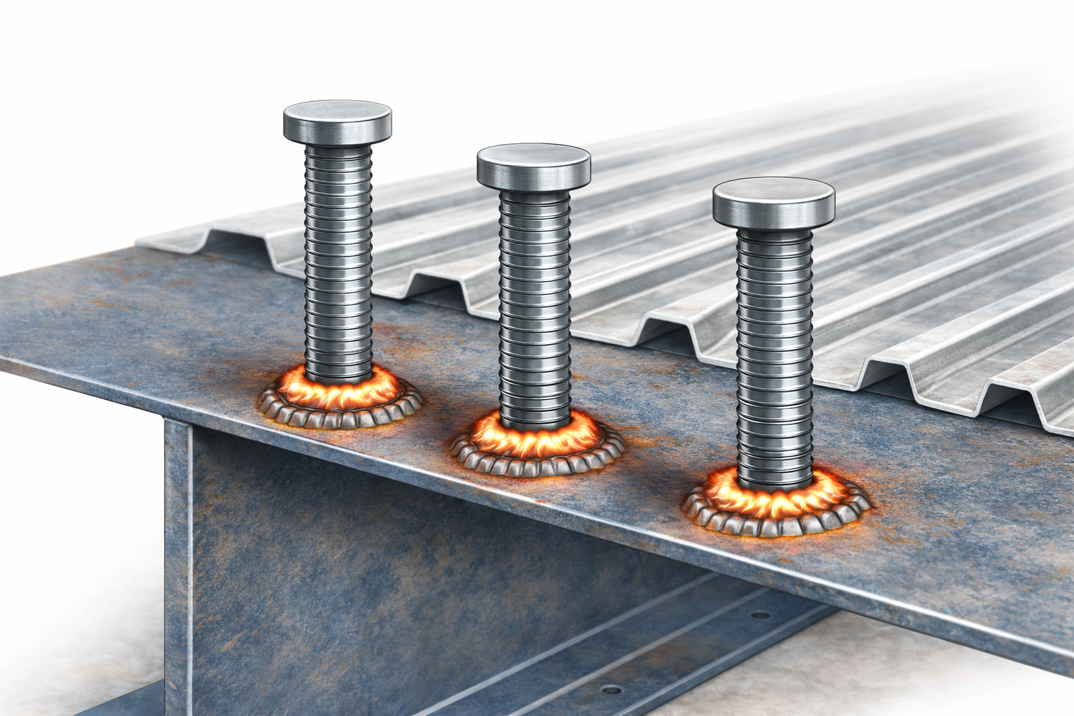
All HCA weld studs are welded by the drawn arc process, not capacitor discharge (CD). The drawn arc process lifts the stud, strikes an arc, and plunges the stud into the molten pool while a ceramic ferrule contains the weld flash. The result is a full-penetration fusion weld that meets AWS D1.1 mechanical requirements.
CD welding is not appropriate for HCA/shear connector diameters. CD is limited to smaller diameters (¼" and below, typically) on thin base material. For 1/2" through 1" HCA studs on structural plate, drawn arc is always the correct process.
Each drawn arc stud requires a ceramic ferrule matched to the stud diameter and application. Standard ferrules are used for direct plate welding. Thru-deck (TD) ferrules are required for composite deck applications where the deck creates a standoff between the ferrule base and the beam flange. See the Weld Stud Ferrule Sizing Chart for matched ferrule part numbers by diameter.
HCA vs. Deformed Bar Anchor: Choosing the Right Stud
Both HCAs and deformed bar anchors (DBAs) are used in concrete connection applications, but they transfer load differently. See the Deformed Bar Anchors Selection Guide for a full comparison. The summary:
| Property | Headed Concrete Anchor (HCA) | Deformed Bar Anchor (DBA) |
|---|---|---|
| Load transfer mechanism | Bearing of head against concrete | Surface interlock along embedded length |
| Design standard | ACI 318 Chapter 17, AISC 360 | ACI 318, project-specific |
| Primary use | Composite decks, embed plates, column bases | Precast concrete, tilt-up, moment connections |
| Embedded surface | Smooth shank -- no surface engagement | Deformed ribs -- continuous bond along length |
| Head requirement | Required -- head provides the bearing surface | None -- no head plate at tip |
Where Headed Concrete Anchors Are Used
- Composite steel-concrete beams: 3/4" and 7/8" shear connectors welded through metal deck to steel beam top flanges. Most common structural steel construction application.
- Embed plates in concrete walls and slabs: Steel plates cast into concrete with HCA studs providing the tension and shear connection. Used for equipment pads, crane rail supports, and structural connections.
- Column base plates: 1/2" to 5/8" HCA studs anchoring base plates to concrete foundations where cast-in-place anchor bolts are not practical.
- Precast panel connections: HCA studs on steel connection hardware embedded in precast concrete panels for field-bolted connections.
- Elevated concrete slabs on steel framing: Composite construction to stiffen and strengthen the slab-beam assembly by engaging the concrete in bending resistance.
- Infrastructure and bridges: Bridge deck composite construction, shear stud connectors on steel girders and composite box beams.
Related Resources
- Weld Stud Selection Guide -- all stud types, process selection, materials overview
- Weld Stud Load Capacities Reference -- complete AWS D1.1 and AISC 360 design value tables
- Deformed Bar Anchors Selection Guide -- when to use DBA vs. HCA
- Threaded Weld Studs Selection Guide -- pitch diameter, full thread, and collar stud types
- Weld Stud Ferrule Sizing Chart -- matched ferrule part numbers by diameter
- Nelson Weld Stud Cross-Reference -- Cox Industries and Bluearc equivalents for Nelson H4L studs
Frequently Asked Questions
What is the difference between a headed concrete anchor and a shear connector?
The stud itself is the same product -- ASTM A108 drawn arc weld stud with a head. The difference is application. HCAs are used for anchoring steel to concrete (governed by ACI 318). Shear connectors are used in composite beam construction to engage the concrete slab in bending (governed by AISC 360). The structural engineer specifies which code applies based on the project requirements.
Do I need to account for weld loss when specifying stud lengths?
Yes. Drawn arc welding consumes material at the weld end. A 1/2" to 5/8" stud loses approximately 3/16" to 1/4" of length during welding. Structural drawings typically specify after-weld length (AWL). When ordering, confirm whether the catalog length is before-weld or after-weld, and adjust accordingly.
Can I use a standard ferrule for thru-deck composite welding?
No. When welding shear connectors through metal deck, use thru-deck (TD) ferrules, not standard full-diameter or pitch-diameter ferrules. The deck creates a standoff between the gun foot and the beam flange, and standard ferrules will not seat correctly. Thru-deck ferrules have a longer base profile designed to contact the beam flange through the deck opening.
What is the maximum stud diameter for composite deck construction?
AISC 360 limits shear connectors in composite deck to a nominal diameter of 3/4". Larger studs do not produce proportionally higher shear capacity in deck applications because the governing failure mode is concrete breakout in the deck rib, not stud fracture. Most composite deck designs use 3/4" x 4-3/16" or 3/4" x 4-3/8" shear connectors.
Does Eugene Fastener carry Nelson brand HCA studs?
No. We stock Cox Industries and Bluearc HCA weld studs, which are equivalent in material (ASTM A108) and geometry to Nelson H4L studs. If your drawings specify Nelson part numbers, use our Nelson cross-reference page to find the matching Cox or Bluearc equivalent we carry.
What stainless steel grade should I use for HCA weld studs in a marine environment?
316 stainless is the preferred grade for marine and chloride-exposed environments due to its molybdenum content, which improves pitting and crevice corrosion resistance compared to 304. Note that stainless weld studs require a separately qualified AWS D1.1 welding procedure -- do not assume your contractor's carbon steel WPS covers stainless studs.