Weld Stud Selection Guide
Weld studs cover a wider range of applications than most fasteners. A 3/4-inch shear connector holds composite floor deck to a structural beam. A 10-24 capacitor discharge stud mounts a cable tie to a painted sheet metal panel. Both are weld studs—but they use different processes, require different equipment, and are governed by entirely different engineering standards. This guide walks through the decision points in order so you can identify the right stud type, welding process, material, and size for your application.
- Drawn arc vs. CD: Use drawn arc for structural, load-bearing work (shear connectors, HCA, DBA, threaded studs 3/16"-1"); use capacitor discharge (CD) for thin-gauge or pre-finished panels (#4-40 to 3/8-16) where the back side must stay clean.
- Common stud types: Headed concrete anchors (HCA), shear connector studs, threaded studs (TP, TF, collar), deformed bar anchors (DBA), and non-threaded/insulation studs each serve a different structural role.
- Picking diameter and length: Diameter is set by load and base metal thickness (see the sizing tables below); order length is always measured before welding, so add 1/8" shrinkage for studs 1/2" and under, or 3/16" for 5/8" and up.
- Ferrules: Every drawn arc weld stud requires a ceramic ferrule matched to diameter and base configuration; most CD applications do not need one.
In stock and shipping from Eugene, OR. Buy by the box, or submit a project for job pricing.
Shop All Weld Studs → Get job pricing / submittalsEugene Fastener stocks headed concrete anchors (HCA), shear connectors, and deformed bar anchors from Cox Industries and Bluearc—both manufactured to ASTM A108 carbon steel specifications and qualified under AWS D1.1. Whether you’re spec’ing a composite beam project or sourcing threaded studs for an equipment mounting application, we can confirm availability, lead time, and pricing.
In This Guide:
- What Is a Weld Stud?
- Drawn Arc vs. CD Welding
- Weld Stud Types
- Material Options
- Sizing Fundamentals
- Welding Process Basics
- Common Applications
- Frequently Asked Questions
What Is a Weld Stud?
A weld stud is a fastener designed to be permanently attached to a base material by an electric arc welding process. Unlike a bolt or screw that passes through material and is secured with a nut or threaded insert, a weld stud fuses directly to the surface of the base metal. The result is a permanent, single-sided threaded or headed attachment point that requires no drilling, tapping, or access to the back side of the panel or structural member.
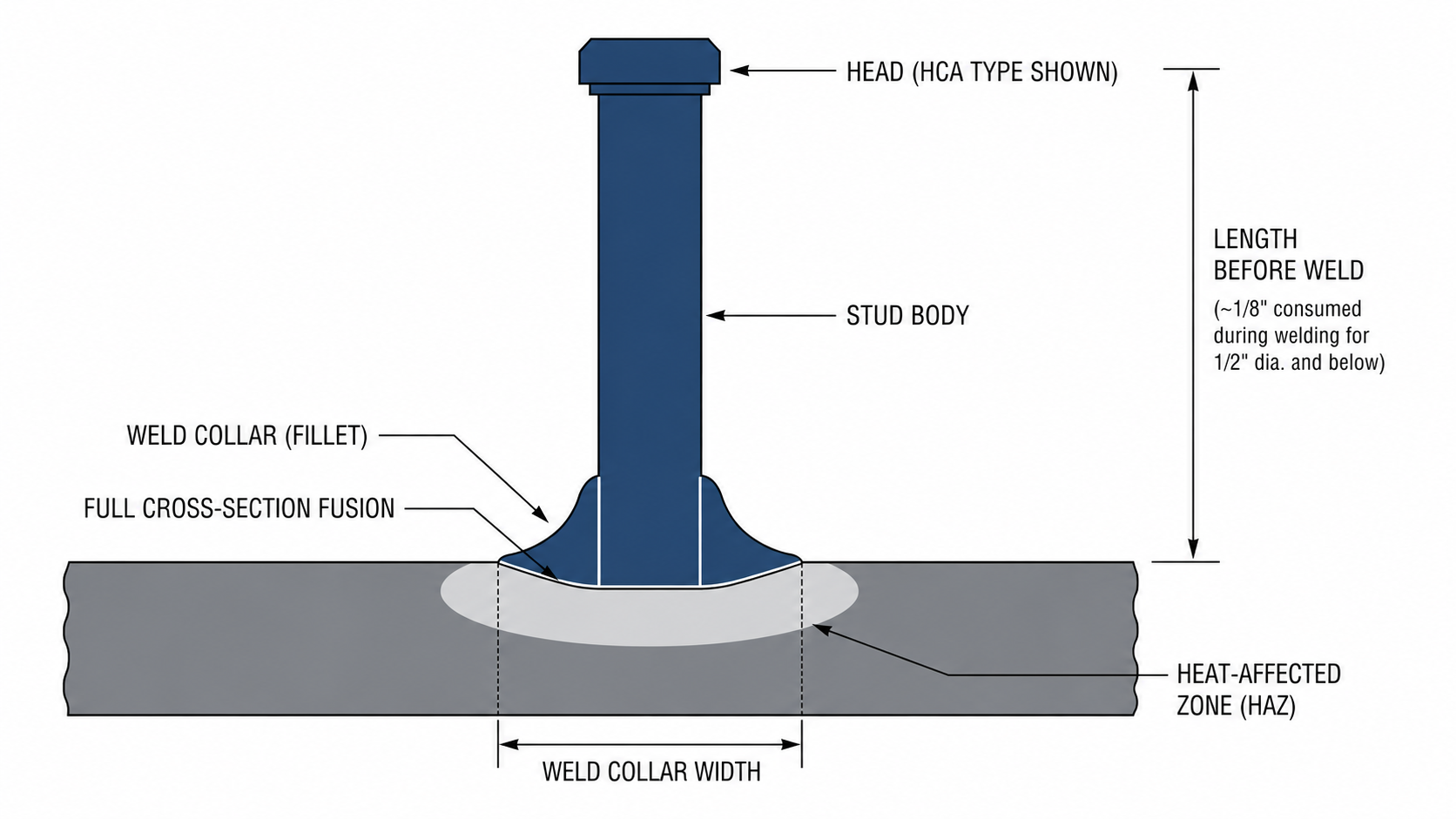
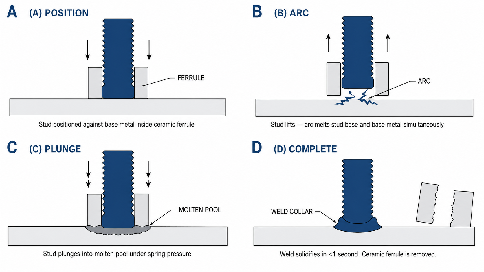
The welding process melts the base end of the stud and a small zone of the base metal simultaneously, then drives the molten stud into the base metal pool under controlled pressure. When the weld solidifies—in less than a second for most applications—the stud is metallurgically bonded to the base metal with full cross-sectional fusion. This produces a joint stronger than the stud itself in most configurations.
Weld studs are used across structural steel construction, precast concrete, heavy manufacturing, HVAC systems, and electronics assembly. The stud form, diameter, and welding process are selected together based on the load the stud must carry, the base metal thickness, and the welding equipment available on the job.
Drawn Arc vs. Capacitor Discharge (CD) Welding
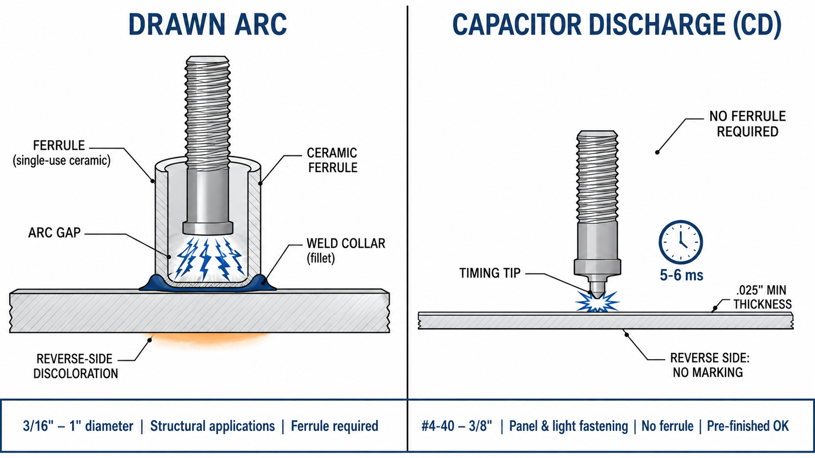
Every weld stud application starts with one decision: drawn arc or capacitor discharge. The two processes use different physics, require different equipment, and suit different stud diameters and base material conditions. Getting this wrong means either an undersized weld joint or visible burn-through on the reverse side of your panel.
Drawn Arc (Arc Stud Welding)
Drawn arc is the structural process. The stud is loaded into a welding gun inside a ceramic ferrule and positioned against the base metal. The gun lifts the stud to create an arc, holds it for a precisely timed interval while the arc melts both the stud base and the adjacent base metal zone, then plunges the stud back into the molten pool. The ceramic ferrule contains the weld and shapes the weld fillet. The result is a full cross-section fusion weld with a visible weld collar around the stud base.
- Stud diameter range: 3/16" through 1" diameter.
- Base metal: Minimum plate thickness scales with stud diameter (see the Sizing section below). Steel and aluminum both supported; minimum thickness for aluminum is higher than for steel.
- Ferrule required: Yes—a ceramic ferrule matched to the stud diameter and base configuration is required for every arc weld stud. See our Weld Stud Ferrule Sizing Chart for part numbers.
- Applications: Shear connectors for composite construction, headed concrete anchors, deformed bar anchors, structural threaded studs—any application where full cross-section weld strength is required.
- Power source: DC arc welding power source. Required amperage scales with stud diameter from 400 amps (up to 7/16") to paired 2,000-amp units (1" diameter). See the Welding Process Basics section below for the full power table.
Capacitor Discharge (CD) Welding
CD welding stores a charge in a bank of capacitors and releases it in 5–6 milliseconds through a small timing tip on the stud base. The extremely fast, concentrated discharge melts only the timing tip and a thin surface zone of the base metal—the stud is simultaneously driven into the weld pool by a spring. Because heat is so localized and brief, the reverse side of the base metal shows virtually no discoloration or distortion, making CD the preferred process when the back surface is painted, polished, anodized, or otherwise finished before welding.
- Stud diameter range: Typically #4-40 through 3/8-16. Smaller diameter range than drawn arc.
- Base metal: Works on base metal as thin as .025" without backup—a key advantage over arc for thin-gauge work.
- Ferrule required: Not required for most CD applications. The 5-6 millisecond weld time is too brief for contamination to affect weld quality in typical conditions.
- Applications: Electronic enclosures, HVAC sheet metal, automotive interiors, cable management, control panels, any thin-gauge or pre-finished assembly where back-surface appearance matters.
- Power source: Dedicated CD stud welder (runs on standard AC power supply). Compact and portable compared to arc welding equipment.
Process Comparison at a Glance
| Factor | Drawn Arc | Capacitor Discharge (CD) |
|---|---|---|
| Typical diameter range | 3/16" to 1" | #4-40 to 3/8" |
| Minimum base metal | .036" and up (varies by stud dia.) | .025" and up |
| Weld time | Fraction of a second to ~1 second | 5–6 milliseconds |
| Reverse-side effect | Discoloration visible on thin metal | Virtually none |
| Pre-finished surfaces | Not recommended | Yes—paint, polish, or anodize before welding |
| Ceramic ferrule | Required per stud diameter and type | Not required (most applications) |
| Structural applications | Yes—shear connectors, HCA, DBA, threaded studs | Light fastening and panel attachment only |
| Power source | DC arc welder (400–2,000+ amps by diameter) | CD stud welder (standard AC power supply) |
Weld Stud Types
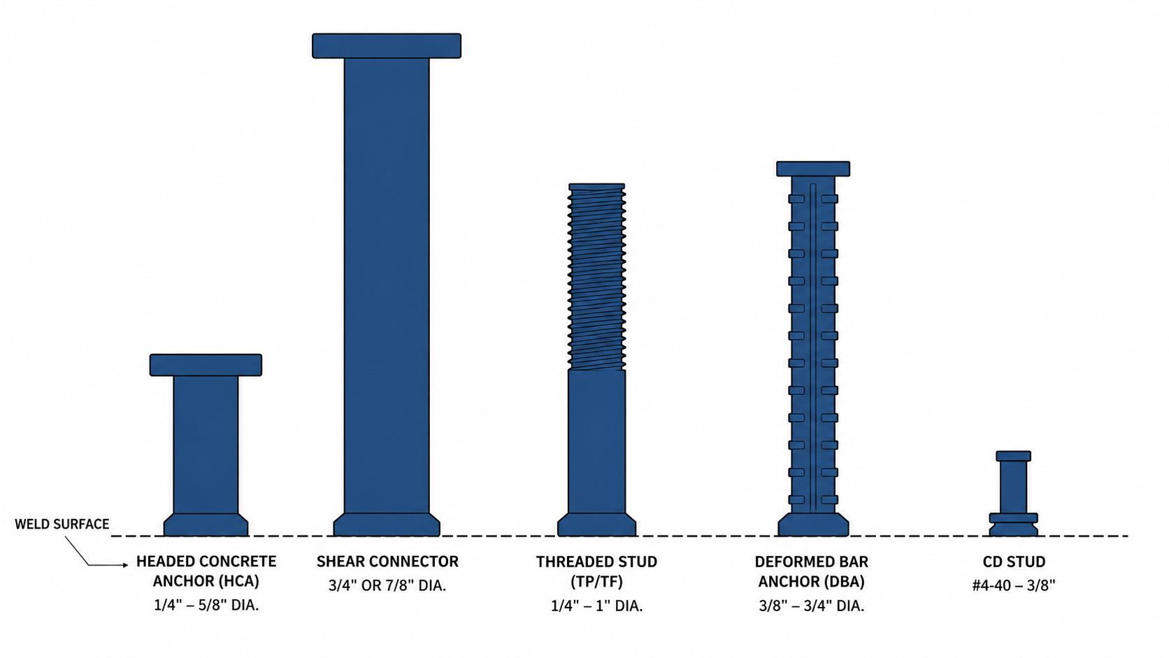
The stud form is selected based on what the stud must do after it’s welded. Is it transferring shear load into a concrete slab? Providing a threaded mounting point? Anchoring a precast panel? Each application calls for a different stud geometry, diameter range, and welding process.
Headed Concrete Anchors (HCA)
Headed concrete anchors are drawn arc studs with a large flat head on the embedded end. The head bears against the surrounding concrete after casting, providing both tensile pullout resistance and shear resistance through direct bearing. HCA studs are the standard anchor for embed plates, loading dock curbs, waterway lock forms, precast window frames, and any application where a threaded protrusion must extend from a concrete surface after the form is stripped.
Eugene Fastener stocks ASTM A108 HCA studs from Cox Industries and Bluearc in common diameters. For sizing guidance, embedment depth recommendations, and capacity considerations, see our Headed Concrete Anchors & Shear Connectors Selection Guide.
Shear Connector Studs
Shear connector studs are the large-diameter headed studs welded through metal deck to a structural steel beam flange, mechanically connecting the steel beam to the overlying concrete slab to create composite construction. When the composite member deflects under load, the shear connectors transfer horizontal shear force between steel and concrete. This composite action can increase effective beam capacity by 30–50% compared to non-composite construction, reducing the steel tonnage and beam depth required in a floor system.
Shear connectors are specified under AISC 360 and AWS D1.1. The standard construction diameters are 3/4" and 7/8". Ferrule configurations vary between standard flange welding (34FER, 78FER) and thru-deck welding (34TFER, 78TFER)—used when studs must be welded through the ribs of metal deck to the beam flange below. For allowable shear and tensile capacity data, see our upcoming Weld Stud Load Capacities & Engineering Reference (guide in progress).
Threaded Studs
Threaded weld studs provide a permanent threaded attachment point on any weldable surface without drilling or tapping the base metal. They eliminate the failure risk of stripped tapped holes in thin-gauge steel and are the standard mounting method for crane rails, elevator guide rails, conduit clamps, structural fixtures, and equipment mounting plates. Several configurations exist depending on whether the thread must be isolated from the weld zone, run the full shank length, or handle a thin-gauge CD application:
- Pitch Diameter Base (TP): The most common drawn arc threaded stud. The weld base diameter equals the thread pitch diameter. Available 1/4"–1" diameter in UNC 2A thread standard. Used for securing clamps, crane rails, elevator rails, and structural fixtures to steel.
- Full Threaded (TF): Thread runs the full length of the shank, maximizing the usable fastening zone. Sizes 10-24 through 1". Common for securing form boards, nailers, prefabricated hangers, and conduit brackets to structural steel.
- Collar Stud (CS): A collar separates the weld base from the threaded shank, keeping the thread clear of weld heat and flash. Sizes 1/4"–1/2". Used where thread condition and clean base appearance are critical.
- CD Threaded Studs: Small-diameter threaded studs (#4-40 through 3/8-16) welded by capacitor discharge. No ferrule required. Available in flanged and non-flanged configurations. The standard choice for panel attachment, cable management, and any thin-gauge or pre-finished sheet metal assembly.
For a complete guide to threaded stud selection including process choice, thread sizing, and application-specific recommendations, see our upcoming Threaded & Headed Studs Selection Guide (guide in progress).
Deformed Bar Anchors (DBA)
Deformed bar anchors are headed weld studs with a deformed (ribbed) shank, similar in profile to deformed reinforcing bar. The deformations increase the mechanical bond between the anchor and the surrounding concrete, improving load transfer under combined tension and shear and reducing the required embedment depth compared to smooth-shank anchors. DBAs are the standard anchor for composite bridge deck construction, heavy precast panels, waterfront infrastructure, and applications where the rebar-like bond development length matters.
Cox Industries DBAs are available in 3/8", 1/2", 5/8", and 3/4" diameters, with standard lengths ranging from 6-1/8" through 36-1/8". For complete DBA specifications and ASTM A1064 references, see our upcoming Deformed Bar Anchors Selection Guide (guide in progress).
Non-Threaded and Insulation Studs
Non-threaded studs (NT) are plain-shank weld studs without any thread or head feature—a fused cylindrical pin. They are used as locating pins, spacers, or where the attachment clip or cable tie is applied to the shank without threading. Insulation studs (IN) are a specific non-threaded form designed for attaching batt or board insulation to metal building walls and roofs. The pin is driven through the insulation face and secured with a speed washer.
Material Options
The stud material must be compatible with both the welding process and the base metal. It must also meet the service environment requirements: carbon steel for structural applications, stainless steel for corrosive environments, aluminum for aluminum base structures.
Carbon Steel (ASTM A108)
Low carbon steel (AISI 1006 to 1022, as cold drawn) is the standard material for virtually all structural weld studs. Cox Industries and Bluearc HCA and shear connector studs are manufactured to ASTM A108 specifications. Mechanical properties as cold drawn: tensile strength 55,000 psi minimum, reduction in area 50% minimum. CD studs use cold drawn low carbon steel with copper flash plating to improve arc initiation. Drawn arc studs are solid fluxed from 1/4" diameter and above.
Carbon steel weld studs can be welded to low carbon steel or stainless steel base metal in the arc process, and to a broader range of base metals in the CD process, including copper alloys and zinc die castings.
Stainless Steel (Type 304, 316)
Stainless steel studs are available in both drawn arc and CD configurations. Type 304 (18-8 chromium-nickel) is the standard stainless grade for most corrosion-resistant weld stud applications. Type 316 adds molybdenum for improved chloride resistance and is the correct choice for marine environments, saltwater exposure, and chemical processing applications.
Important: Type 303 stainless steel (the free-machining grade) is not suitable for weld studs. The sulfur and selenium additives that improve machinability create porosity in the weld and produce an unreliable joint. Always specify Type 304 or 316 for stainless weld studs.
Stainless studs can be welded to low carbon steel base metal (for mixed-material assemblies) or to stainless steel base metal in both arc and CD processes. Where increased ductility is required, stainless studs can be specified annealed to 90 Rockwell B at order time.
Aluminum
Aluminum weld studs are available for both drawn arc and CD applications. Drawn arc uses 5000 series aluminum studs on 5000 series aluminum base metal. The CD process broadens aluminum stud compatibility to include 1100 and 5000 series studs on 1100, 5000 series, and 6061/6063 alloy base metal. Aluminum welding requires a clean, oxide-free surface and appropriate flux or shielding.
Aluminum weld studs are less common than carbon steel in distributor stock. If you need aluminum weld studs for a specific application, contact us with the alloy, diameter, and quantity—we can source through Cox Industries on standard lead times.
| Material | Specification | Arc Process | CD Process | Best For |
|---|---|---|---|---|
| Carbon steel | ASTM A108, AISI 1006–1022 | Yes | Yes | Structural, shear connectors, HCA, general industrial |
| Stainless 304 | AISI 304, 18-8 | Yes | Yes | Corrosive environments, outdoor, food processing |
| Stainless 316 | AISI 316, with Mo | Yes | Yes | Marine, saltwater, chloride exposure |
| Aluminum | 5000 series (arc); 1100/5000/6061 (CD) | Yes (5000 series) | Yes (broader alloy range) | Aluminum structure, weight-critical, non-magnetic |
Sizing Fundamentals
Specifying a weld stud correctly requires four parameters: diameter, length, thread designation (for threaded types), and base end configuration. Getting the length wrong is the most common ordering mistake, because weld stud length is always measured before welding.
Diameter
Stud diameter refers to the body or shank diameter, not the weld base (which may be larger depending on stud type). For threaded studs, the diameter is the nominal thread diameter. Common in-stock drawn arc diameters at Eugene Fastener: 3/16", 1/4", 5/16", 3/8", 7/16", 1/2", 5/8", 3/4", 7/8", and 1". CD studs cover #4-40 through 3/8-16 thread sizes.
Length Before Weld
Order length is the stud length before welding. The arc process consumes a small amount of the stud base during welding, so the finished (after-weld) length is slightly shorter than the ordered length. Calculate your required order length by taking the protruding length you need after welding and adding the weld shrinkage allowance:
- Studs 1/2" diameter and below: add 1/8" to your required finished length.
- Studs 5/8" diameter and above: add 3/16" to your required finished length.
Example: You need a 1/2" diameter threaded stud to protrude 4" from the base metal surface after welding. Order length = 4" + 1/8" shrinkage = 4-1/8" order length.
Thread Designation
Standard thread is UNC 2A (Unified National Coarse, Class 2A tolerance) for all common drawn arc and collar studs. The 10-32 CD stud thread is UNF 2A. Maximum standard thread length on TP pitch diameter studs is 3-7/8". Metric thread weld studs are available as non-stock special orders—contact us with the metric size, diameter, and quantity.
Minimum Base Metal Thickness for Arc Welding (Steel)
Arc welding requires sufficient base metal mass to absorb weld heat without burn-through. Minimum plate thickness for steel without backup, by stud diameter, from Cox Industries published data:
| Stud Diameter | Min. Steel Plate (in.) | Approx. Sheet Gauge |
|---|---|---|
| 3/16" | .036" | 20 gauge |
| 1/4" | .048" | 18 gauge |
| 5/16" | .060" | 16 gauge |
| 3/8" | .075" | 14 gauge |
| 7/16" | .090" | 13 gauge |
| 1/2" | .120" | 11 gauge |
| 5/8" | .145" | — |
| 3/4" | .185" | — |
| 7/8" | .250" | — |
| 1" | .375" | — |
Reference Data Disclaimer. Minimum plate thickness values are sourced from Cox Industries published data for arc stud welding in flat steel stock without backup, under laboratory conditions. Actual minimum thickness in your application depends on base metal grade and condition, heat sink effects from adjacent welds or backup bars, and equipment calibration. These values are reference data for planning purposes. For application-specific qualification, consult your stud welding equipment supplier and refer to AWS D1.1. Eugene Fastener & Supply provides this data as a reference and does not warrant performance for any specific application beyond the conditions described in the source data.
Welding Process Basics
This section covers the fundamental setup considerations for stud welding. It is not a substitute for your stud welding equipment operating manual or for AWS D1.1 qualification requirements on structural applications. For detailed procedural guidance, work with your equipment supplier or a certified welding engineer.
Power Source Requirements (Arc Welding)
Arc stud welding power requirements scale with stud diameter. An undersized power source leads to cold welds with inadequate fusion; an oversized source can cause burn-through. Standard guidelines from Cox Industries:
- Up to 7/16" diameter: 400 amp NEMA-rated DC arc welder.
- Up to 1/2" diameter: 600 amp NEMA-rated DC arc welder.
- Up to 5/8" diameter: Two 400 amp welders in parallel.
- Up to 3/4" diameter: Two 600 amp welders in parallel.
- Up to 7/8" diameter: 2,000 amp dedicated stud welding power unit.
- Up to 1" diameter: Two 2,000 amp power units in parallel.
Ferrule Selection
The ceramic ferrule is matched to the stud diameter and the base configuration (full diameter, pitch diameter, thru-deck, angle). Ferrules are disposable single-use components. Using the wrong ferrule type results in a malformed weld collar or inadequate shielding of the weld pool. For the complete ferrule part number cross-reference, see our Weld Stud Ferrule Sizing Chart. Note that ferrule tolerances are broader than machined fastener tolerances—do not use a ferrule as a fixture point if exact weld stud location is required.
Surface Preparation
Arc welding is sensitive to surface contamination. The base metal at the weld location must be free of mill scale, heavy rust, paint, galvanizing, and heavy oil. Light surface oil burns off during the arc process, but heavy coatings will cause weld porosity or joint failure. CD welding tolerates pre-finished surfaces better than arc welding, but the weld tip area should still be clean and dry.
When welding on galvanized steel, grind the zinc coating away at the weld location before arc welding. Welding through galvanizing generates zinc vapor, which is a respiratory hazard and causes weld porosity. Work in a ventilated area and use appropriate respiratory protection (N95 minimum; P100 recommended). Follow OSHA guidance on zinc fume exposure limits.
Common Applications
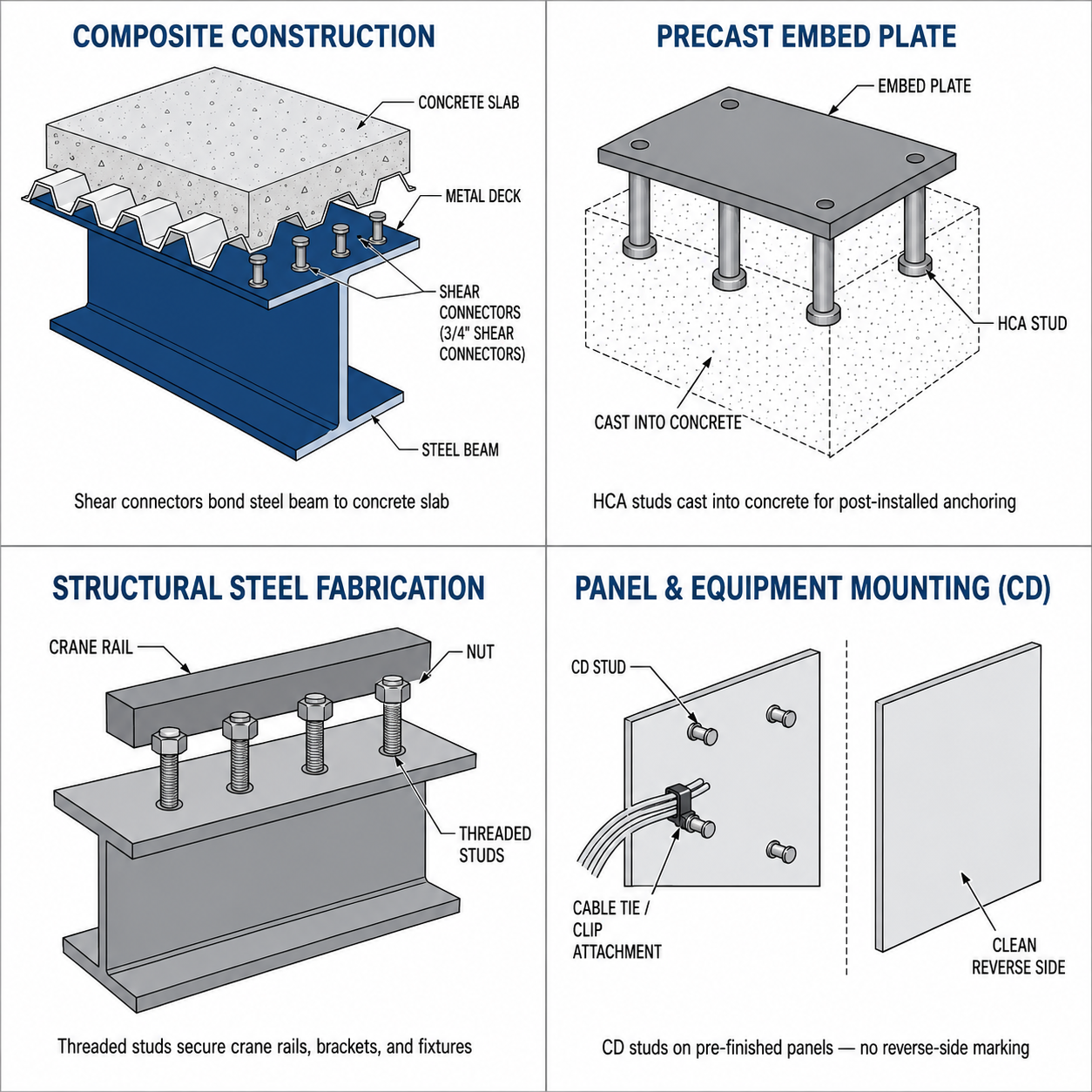
Composite Steel-Concrete Construction
The largest volume application of weld studs in North American construction. Structural steel beams in floor and bridge systems are welded with 3/4" or 7/8" shear connector studs—either directly to the top flange or through the ribs of ribbed metal deck. The composite action between the steel beam and the concrete slab above can increase the effective member capacity by 30–50% compared to non-composite construction, reducing required steel tonnage and beam depth in a floor system. Applications include office buildings, parking structures, steel bridges, and industrial facilities.
Precast and Cast-in-Place Concrete
Headed concrete anchors (HCA) are welded to embed plates before the plate is cast into a concrete element, providing post-installation threaded or headed attachment points for mechanical equipment, handrails, curtain walls, and façade cladding systems. Deformed bar anchors (DBA) serve a similar function where rebar-like bond development is required in heavy precast panels, bridge deck elements, and waterfront or infrastructure components. Both stud types are welded to the embed plate in the fabrication shop, not in the field.
Structural Steel Fabrication
Threaded weld studs replace drilled-and-tapped holes in structural steel fabrication work. Common applications include securing crane rails to runway beams, mounting elevator guide rails to steel columns, attaching insulated panels to structural framing, securing conduit clamps and cable trays to beams, and providing fastening points on embed plates where post-installation bolting is required. Pitch diameter (TP) and full-threaded (TF) configurations are standard for these applications.
Metal Building, HVAC, and Insulation
Insulation studs (IN) are welded to the interior faces of metal building walls and roofs to secure batt or board insulation without penetrating the exterior skin. The pin is driven through the insulation face and a speed washer is pressed over the pin to capture it. CD threaded studs serve a parallel panel attachment function in HVAC ductwork, electrical enclosures, and equipment panels where back-surface appearance or thin gauge metal rules out arc welding.
Electronics and Equipment Assembly
CD studs are the precision fastening solution for thin-gauge and pre-finished metal assemblies. The 5–6 millisecond CD weld time leaves virtually no reverse-side marking, making it the standard process for electrical enclosure manufacturing, automotive interiors, control panels, and any assembly where appearance on the non-welding side is a product requirement. The #4-40 through 3/8-16 thread range covers nearly all light-gauge panel attachment applications.
Frequently Asked Questions
What is the difference between a shear connector and a headed concrete anchor?
Both are headed drawn arc weld studs, but they serve different structural functions and come in different size ranges. Shear connectors (3/4" and 7/8" diameter) are designed specifically for composite construction: they transfer horizontal shear between a structural steel beam and an overlying concrete slab and are specified under AISC 360 and qualified under AWS D1.1 shear connector provisions. Headed concrete anchors (HCA, typically 1/4"–5/8" diameter) are embed plate anchors designed primarily for tension and combined tension/shear loads in precast and cast-in-place concrete. They are not interchangeable.
What is a weld stud ferrule and do I always need one?
A ferrule is a single-use ceramic ring that slips over the base of a drawn arc weld stud before welding. It serves three functions: it contains the molten weld pool during the arc process, it shapes the weld fillet (collar), and it limits oxygen exposure at the weld zone. You need a ferrule for all drawn arc weld studs. You do not need a ferrule for most capacitor discharge (CD) applications because the 5–6 millisecond CD weld time is too short for contamination to affect weld quality under typical conditions. Use our Ferrule Sizing Chart to match the correct part number to your stud diameter and base configuration.
Can I use weld studs on galvanized steel?
Yes, with precautions. For arc welding, grind the zinc coating away at the weld location before welding. Welding through galvanizing generates zinc vapor, which is a respiratory hazard and causes weld porosity. Work in a ventilated area and use appropriate respiratory protection. For CD welding on thin galvanized panels, the localized, brief heat of the CD process limits zinc vapor generation, but weld quality can still be affected—test the weld procedure on sample material before production.
What does “length before weld” mean?
Weld stud length is always specified and measured before the stud is welded. The arc process consumes a small amount of the stud base, so the finished after-weld length is slightly shorter than the ordered length. For studs 1/2" diameter and below, the finished length is approximately 1/8" shorter than ordered. For studs 5/8" and above, approximately 3/16" shorter. Always specify the length you need after welding and add the appropriate shrinkage allowance when placing your order.
What specification should I call out for headed concrete anchor weld studs?
The standard material specification for carbon steel weld studs in structural applications is ASTM A108 (Standard Specification for Steel Bar, Carbon and Alloy, Cold Finished). For composite construction (shear connectors), the relevant welding qualification standard is AWS D1.1 (Structural Welding Code — Steel). On project submittals, call out ASTM A108 material and AWS D1.1 welding qualification for drawn arc studs. The Cox Industries and Bluearc HCA and shear connector studs we stock are manufactured to these specifications.
Can I weld carbon steel studs to stainless steel base metal?
Yes. Both arc and CD processes support welding low carbon steel studs to 300 series stainless steel base metal. You can also weld stainless studs to low carbon steel base metal. Stainless stud to stainless base metal is also fully supported. The one exception is Type 303 stainless (the free-machining grade): its sulfur content creates weld porosity and it should never be used as a weld stud or as the base metal for stud welding without prior qualification testing.
How do I calculate order length for an embed plate application?
Start with the required embedment depth per your structural engineer’s specification. Add the embed plate thickness (the stud must protrude through the plate). Add the weld shrinkage allowance (1/8" for 1/2" diameter and below; 3/16" for 5/8" and above). Example: 4" embedment + 1/2" plate + 1/8" shrinkage = 4-5/8" order length for 1/2" diameter studs.
Do you stock weld studs for fast shipment?
We stock Cox Industries HCA and shear connector studs in the most common diameters and lengths. For project quantities or less-common sizes, typical lead times are 1–2 weeks. Submit your BOM or stud schedule and we will confirm availability, pricing, and lead time. Orders over $4,000 ship free. Call (541) 342-5978 or request a quote online.
Ready to Order Weld Studs?
Eugene Fastener stocks ASTM A108 headed concrete anchors and shear connectors from Cox Industries and Bluearc. Volume pricing for project quantities. Free shipping on orders over $4,000—most structural stud projects qualify.
Include stud type, diameter, length, material grade, quantity, ship-to ZIP, and need-by date for fastest quoting. Attach your BOM or stud schedule if available.
Related Resources
- Weld Stud Ferrule Sizing Chart — match ferrule part numbers to every stud diameter and base configuration for drawn arc welding
- Headed Concrete Anchors & Shear Connectors Selection Guide — sizing, embedment, and application guidance for HCA and shear connector studs
- Threaded Weld Studs Selection Guide — detailed guide to TP, TF, collar, and CD threaded stud types
- Deformed Bar Anchors Selection Guide — DBA specifications, precast and tilt-up applications, and drawn arc process requirements
- Weld Stud Load Capacities & Engineering Reference (coming soon) — allowable shear and tensile values by diameter for structural design
- Technical Resource Center — all guides and reference articles